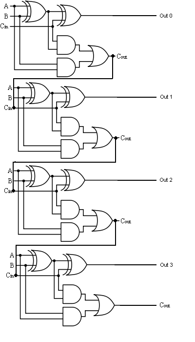
Logic Diagram Of 4 Bit Adder
Glossary of electronic and engineering terms, ic adder chip Adder logic binary circuit gates diagram using array make inputs labeled twice below also used Full adder circuit diagram
Glossary of Electronic and Engineering Terms, IC Adder Chip
Logic diagram of 4 bit full adder The answer is 42!!: four bit full adder tutorial Adder circuit binary logic output sum xor electronics theorycircuit boolean diagrams derived
Adder logic multiplexer lookahead vhdl
Adder ic chip bit circuit chips schematic circuits ttl gr nextAdder bit four logic gates byte 4bit nand boolean nor values possible possibilities hold answer trick function known any well A binary adder made using and-or array logicDownload 4 bit adder circuit stick and logic diagram.
.


