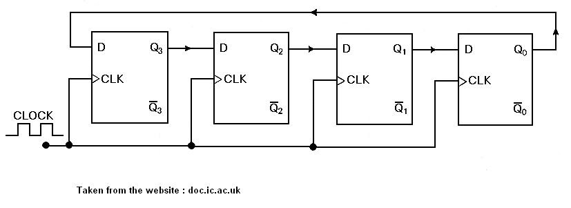
4 Bit Counter Circuit Diagram
4-bit ripple counter Counter bit flip using binary flops circuit output q3 collected q1 q2 q0 would final Counters binary circuitverse synchronous 4bit 1111
Circuit Design of a 4-bit Binary Counter Using D Flip-flops - VLSIFacts
Counter bit state diagram flip binary using circuit flops table truth draw ff construct let 17. the bcd (mod10) synchronous up counter circuit constructed with d Circuit design of a 4-bit binary counter using d flip-flops – vlsifacts
Diagram counter down bit block circuit precautions
Synchronous bcd mod10 flops constructed murat fig194 bit down counter Counter fig84 bit up down counter truth table.
Schematic design of a 4-bit ring counterRing counter bit verilog code vhdl diagram example tips testbench ckt tricks coding written 16. the 4 bit synchronous up counter circuit constructed with tCounter bit down circuit diagram digital.
![Circuit Design of a 4-bit Binary Counter Using D Flip-flops - VLSIFacts](https://i2.wp.com/www.vlsifacts.com/wp-content/uploads/2015/11/4-bit-counter-state-diagram-VLSIF.png)
Counter bit ripple circuit electronics circuits simulator simulation
Truth table calculator with stepsCircuit design of a 4-bit binary counter using d flip-flops Flip synchronous circuit flops constructedCircuit design of a 4-bit binary counter using d flip-flops – vlsifacts.
Asynchronous synchronous truth steps countersFlop binary flops construct Vhdl coding tips and tricks: example : 4 bit ring counter with testbench.
![Schematic design of a 4-bit ring counter | Download Scientific Diagram](https://i2.wp.com/www.researchgate.net/profile/Mehdi_Askari5/publication/276276612/figure/download/fig8/AS:294560828805128@1447240182572/Schematic-design-of-a-4-bit-ring-counter.png)
![4 Bit Up Down Counter Truth Table | Letter G Decoration](https://i2.wp.com/learn.circuitverse.org/assets/images/4bit_up_counter.png)
![4 Bit Down Counter](https://i2.wp.com/www.petervis.com/dictionary-of-digital-terms/4-bit-down-counter/4-bit-down-counter-circuit-diagram.gif)
![Circuit Design of a 4-bit Binary Counter Using D Flip-flops – VLSIFacts](https://i2.wp.com/www.vlsifacts.com/wp-content/uploads/2015/11/4-bit-counter-Final-VLSIF.jpg)
![16. The 4 bit synchronous up counter circuit constructed with T](https://i2.wp.com/www.researchgate.net/profile/Murat_Uzam/publication/319203501/figure/download/fig18/AS:529761928531972@1503316494604/The-4-bit-synchronous-up-counter-circuit-constructed-with-T-flip-flops.png)
![DeldSim - 4-Bit Down Counter](https://i2.wp.com/www.deldsim.com/circuit_diagram/47.png)
![4-Bit Ripple Counter - Circuit Simulator](https://i2.wp.com/indiabix.com/_files/images/electronics-circuits/4-bit-ripple-counter.png)
![Circuit Design of a 4-bit Binary Counter Using D Flip-flops – VLSIFacts](https://i2.wp.com/www.vlsifacts.com/wp-content/uploads/2015/11/4-bit-counter-state-diagram-VLSIF.png)
![17. The BCD (MOD10) synchronous up counter circuit constructed with D](https://i2.wp.com/www.researchgate.net/profile/Murat_Uzam/publication/319203501/figure/download/fig19/AS:529761929371659@1503316494668/The-BCD-MOD10-synchronous-up-counter-circuit-constructed-with-D-flip-flops.png)
![Truth Table Calculator With Steps | Elcho Table](https://i2.wp.com/circuitdigest.com/sites/default/files/projectimage_tut/Asynchronous-Counter.png)